
Ice Bath Failure Modes

The purpose of studying failure modes is to learn how to avoid them. This may seem obvious, but I have to emphasize it, because I don’t want my text to be misinterpreted as being “negative.” I see it as being precautionary, because the failure of an ice bath would be a catastrophic event that I would like to avoid.
First, the parameters. A portable ice bath must bear a static load which may include:
A patient, who may weigh 200 lbs or more.
At least 30 lbs of ice.
At least 10 gallons of water, weighing 80 lbs.
A chest compression device, probably weighing around 20 lbs.
Possibly a liquid-ventilation device, weighing 50 lbs.
Probably a hollow platform to circulate water under the patient, adding 20 lbs to the total weight.
Pumps and tubing, weighing another 10 lbs.
These numbers are approximate because I am unable to find records citing specifics from actual cases. However, in a worst-case scenario, I believe the total weight may approach 500 lbs, which is a quarter of a ton.
This is nontrivial, especially when you consider that the ice bath doesn’t only have to withstand a static load. There are dynamic forces to consider, such as the downward impulses of the chest compression device, and severe vibration if legs supporting the bath have wheels that roll over a rough surface. Vertical acceleration will be inflicted on the ice bath if it is transported in the back of a truck that travels over a bumpy road, and there will be lateral forces when the truck goes around corners or stops abruptly.
In a previous text I provided some historical perspective on ice baths. Now I will explore modes of construction that may be used in an effort to withstand these forces and avoid mechanical failure.
Beam Bridges
The biggest challenge to the structure of an ice bath occurs when people lift it by its opposite ends, leaving it unsupported in the middle. I’ll refer to this as the opposite-ends scenario, in which the bath is like a bridge with a load exerting a downward force that is unsupported in the center of the span.
This comparison is slightly misleading, as bridges are firmly planted on solid foundations, whereas an ice bath will be moved around in unpredictable ways. Still, prior art in bridge design is relevant and should not be ignored.
A beam bridge is the simplest and most basic form, consisting of two or more horizontal beams. In a railroad bridge, the beams are often fabricated from steel, while in a highway bridge, reinforced concrete has become common. A beam bridge is relatively cheap compared with more complicated geometries, and is quick to build, but has an obvious potential problem: It is liable to bend in the middle. Significant bending is unacceptable in bridges that support highways or railroads, but in an ice bath, some bending may be tolerable. The question is, how much bending may occur before the beam fails.
Fortunately, the most readily available materials may tolerate significant bending. As a quick test, I found a piece of square hardwood dowel in my workshop, measuring 3/4" x 3/4" x 3 feet long. I also found an equal length of round aluminum tube, 3/4" in diameter, with walls 0.04" thick. Figure 1 shows the tube with its ends supported and a 25 lb weight in the center. I measured a deflection of about 1/2", and the tube straightened spontaneously when the weight was removed. By comparison, the wood sagged less, to about 1/4", and likewise straightened itself after it was unloaded.
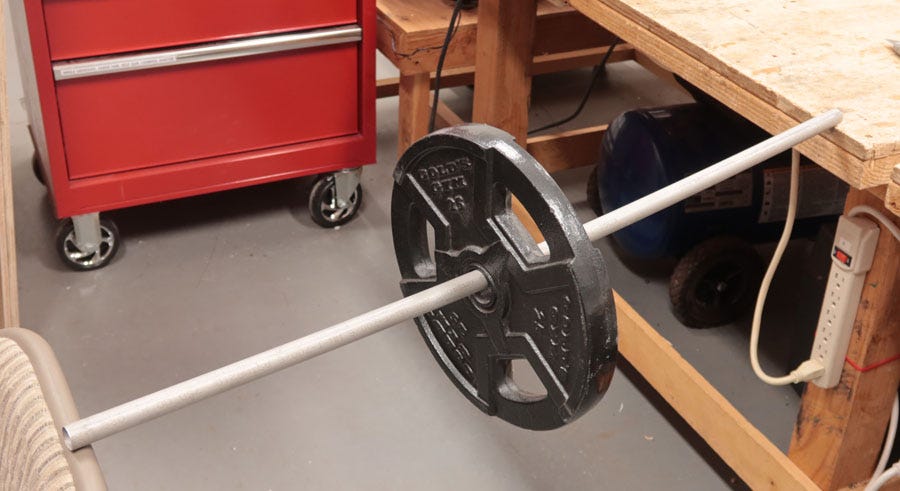
Figure 1. A basic strength test.
The aluminum would be cheaper than the wood, and much lighter; but some people find it more difficult to work with. Still, either material could be used. Bearing this in mind, why haven’t cryonics organizations fabricated ice baths using horizontal lengths of wood or tubing?
They have. The very first ice bath (sometimes referred to as a “Pizer tank” in honor of David Pizer, who designed it) used a sheet of plywood which functioned as a rather wide, relatively thin beam. It measured approximately 2 feet by 7 feet by 3/4" thick. The bath also had a rail consisting of PVC water pipe, to support a vinyl liner, but I don’t think the rail added significantly to the rigidity of the plywood, because it was in sections that were not very securely anchored to the plywood. Figure 2 shows a Pizer tank photographed in the home of cryonics pioneer Curtis Henderson around 1996. (The semicircular tubes were perforated, to spray water over the upper surface of the patient.)
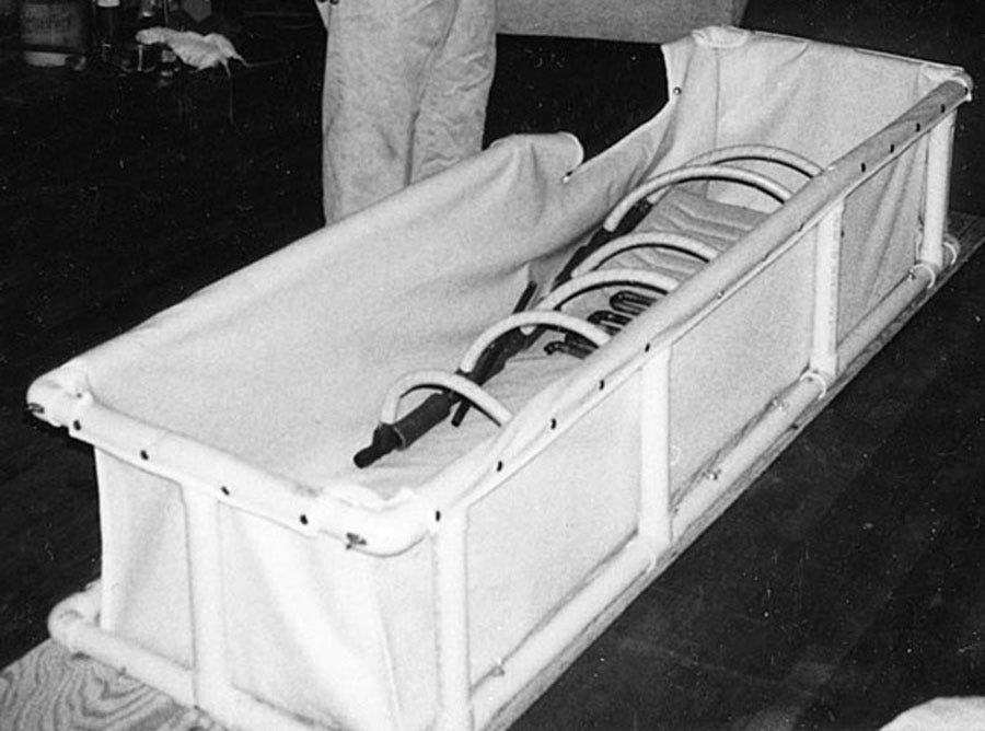
Figure 2. The Pizer bath was mounted on a sheet of 3/4" plywood.
The Pizer tank probably flexed a little when it carried a patient with ice and water, but there is no record of it ever breaking. It was fairly heavy, weighing around 60 lbs empty, including the PVC pipe, a water pump, and the semicircular tubing. However, that was a manageable weight. The real drawbacks were that it looked home-made and was not collapsible. The home-made appearance could create a very bad impression in any conventional medical environment, and its noncollapsible structure prevented deployment via a scheduled airline or any ground vehicle with a load bed shorter than 7 feet.
You might imagine an alternative consisting of metal tubing in sections that could be plugged together on-site. This would make the ice bath collapsible and transportable, and it should look more acceptable.
At Alcor Foundation, Steve Graber designed an elegant ice bath on this basis. I believe it was fabricated from steel tubing 1" in diameter. (Graber has not contributed to this text.) The sections are transportable in a bag, and I photographed him assembling them in figures 3, 4, and 5.
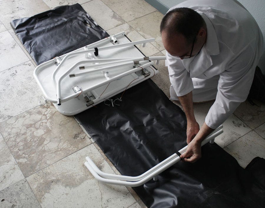
Figure 3. At Alcor Foundation in Scottsdale, Arizona, Steve Graber begins to assemble the ice bath that he designed and fabricated.
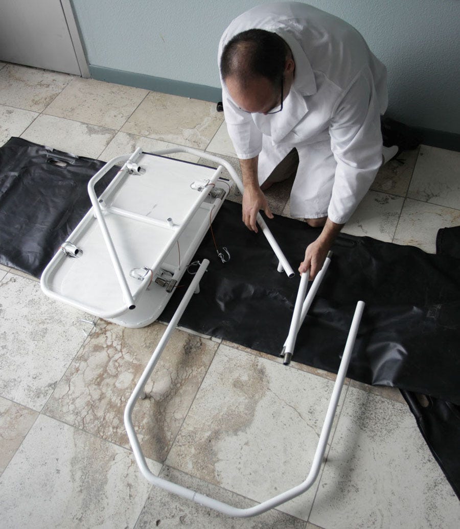
Figure 4. Halfway through assembly of the Graber ice bath.
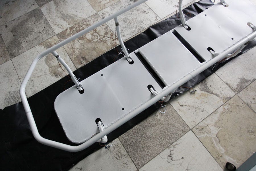
Figure 5. The black plastic under the ice bath is a liner which will be located inside the frame.
Personally I prefer ice baths that don’t require assembly from separate parts, because a standby-transport team working against the clock may suffer from stress-induced confusion. Parts may be misassembled, or they may be misplaced. But leaving that issue to one side, the Graber design is still fundamentally a beam bridge (actually consisting of four beams, if you count the two side rails and the two tubes along the edges of the base). And horizontal beams suffer from an unfortunate mathematical law. If a beam is supported at each end, the deflection at the center is proportional with the third power of its length. (This is only true if the load remains constant. If the load increases in proportion with the length, then the deflection is proportional with the fourth power of the length).
For those who are unfamiliar with exponentials, I will return to the piece of aluminum tube that I tested in my workshop. Since the tube was 36" long, and its deflection was 1/2", we can write a third-power formula like this (in which I am using asterisks as multiplication signs):
3 * 3 * 3 = k * 0.5
The 0.5 figure is the approximate downward deflection that I measured in inches, and k is a constant derived from the weight applied to the beam and the properties of its materials. (In reality, k may vary slightly as the deflection increases.)
Do the math, and in this instance, the value of k for this weight, using the aluminum tube specified, appears to be 54.
Now imagine that the length of the tube is doubled to 6 feet. If I want to know how much this longer tube will sag in the middle, I will reuse the value for k that I found in the previous formula, and write a new formula like this:
6 * 6 * 6 = 54 * d
Where d is the new deflection. Do the math, and the deflection now works out at 4". In other words, doubling the length of the beam has made it sag 8 times as much.
Of course, there are ways to deal with this problem. Most obviously, the beam can be thicker. But this, of course, increases the weight of the ice bath, which is an important factor for teams who are hauling equipment out to a standby. Another option is to use a stronger material, such as steel instead of aluminum—and indeed, Steve Graber seems to have used steel tubing. He also used multiple tubes, as I noted above.
However, the exponential rate of increase in deflection means that beyond a certain length, round tubing tends collapse unexpectedly, as shown in Figure 6.
At what point does this happen? Steve has a lot more experience working with metal than I do, and I feel sure that he used that experience, or some standard reference texts, to estimate the load-carrying capacity of his design. Personally, I have less experience, and I have been accused more than once of “over-building.” A kinder way to put it is that I tend to be very cautious.
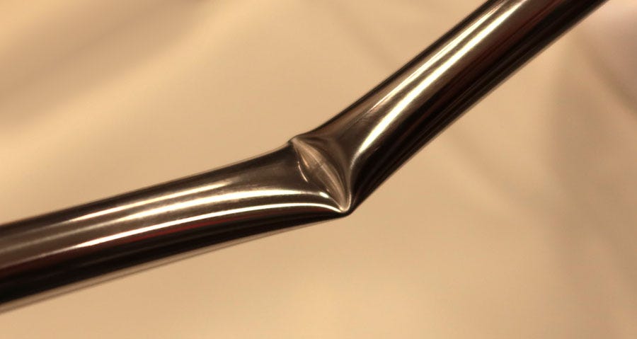
Figure 6. A piece of round tubing that was weighted beyond its limits.
One precaution would be to fabricate a horizontal beam from square-section tubing instead of round tubing. Another precaution would be to support it in the middle somehow.
I exercised both of these precautions when I was managing Suspended Animation, Inc., in Florida, and hired a master welder who fabricated the ice bath shown in Figure 7. Although it uses two horizontal beams to support the platform on which the patient rests, the three legs on each side of the bath support the beams at multiple points (circled). Also, I used stainless-steel tubing with a square cross-section.
This design was not collapsible (with the exception of the ends, which could be partially folded to navigate through small spaces or into elevators). It was designed to roll into a vehicle with substantial head room, via a lift gate or a ramp.
Was this design more robust than the Graber design? I don’t know, because neither of them has ever been tested to destruction. Automobile manufacturers can ram a car into a concrete block, just to see what happens, but cryonics organizations lack the resources to do that kind of thing to an ice bath.
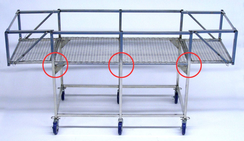
Figure 7. An ice bath built at Suspended Animation, Inc. The horizontal tubing is welded to the legs at three points, circled.
My nonfolding ice bath didn’t require much creative thought, but I also had to design one that was collapsible, with detachable legs. Since this would not be supported in the middle, the opposite-ends scenario became a threat that I had to address.
I chose an alternative to a horizontal beam, known as a truss.
Truss Designs
In engineering and architecture, a truss is a web of straight sections that join together to form triangles, such as the basic bridge configuration in Figure 9. This design has a higher strength-to-weight ratio than a beam (generally speaking), and near-zero deflection.
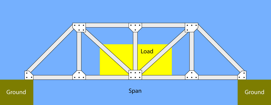
Figure 9. This common style of bridge is known as a truss.
A truss always consists of triangles, because a triangle is the only straight-sided polygon that refuses to change its shape under stress. (Even the rectilinear ice bath in Figure 7 includes small solid triangular plates, visible in two of the circles, to strengthen the welded joints.)
A truss is more complicated than it looks. When you observe a bridge such as the one in Figure 9, it sits across a river or a narrow valley without any sign of stress or strain. But its structure is constantly experiencing a complicated and contradictory web of forces, of two main types: Compression and tension.
Figure 10 shows the same imaginary bridge with red indicating sections experiencing tension, and green indicating sections experiencing compression. The red sections are properly known as ties, while the green sections are called struts. The gray sections have little or no net force acting on them, but are necessary to stabilize the structure. The plates that connect the struts and ties are known as gusset plates.
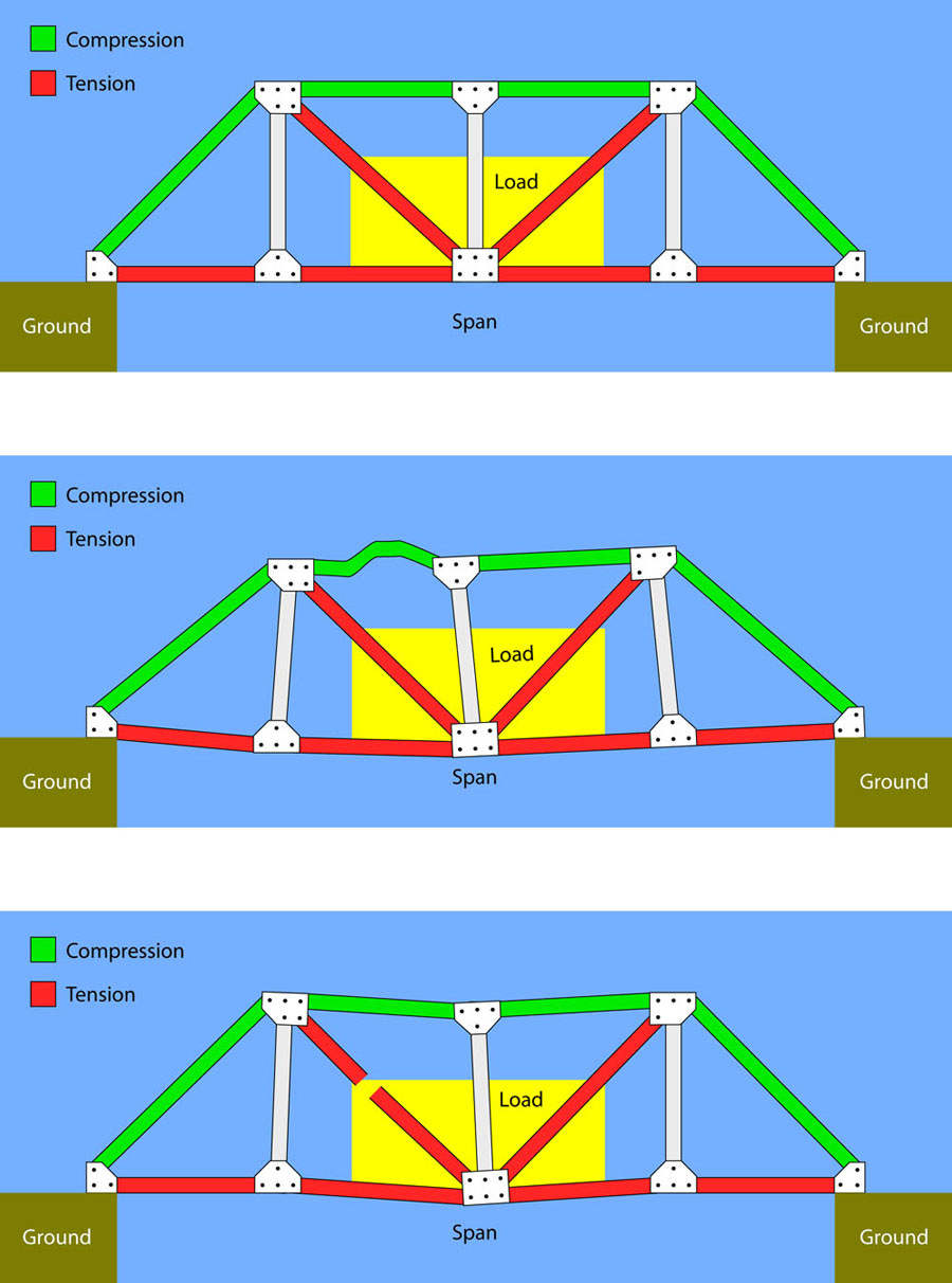
Figure 10. A bridge created as a truss. In the example in the center, a strut bends under compression forces. In the example at the bottom, a tie comes apart under tension forces.
How can you tell if a section is under tension or compression? You can try to imagine what happens if it fails. Figure 10 shows two failure modes. In the center scenario, compression forces have caused a strut to bend, while in the bottom scenario, tension caused a tie to come apart in the middle.
In reality, bridge failures are likely to be age-related, as steel may be weakened by rust, or concrete foundations may develop cracks, allowing corrosion of the rebar inside. Such factors seem irrelevant to an ice bath, but still, if a truss is used, we need to understand how the compression and tension forces will interact.
Figure 11 shows a simplified rendering of the first collapsible, portable design that I came up with, initially for Suspended Animation, and more recently for Biostasis Technologies. The figure uses the same color scheme as in Figure 10 to distinguish struts from ties. The ice bath can be supported by two legs, as shown.
When I made the version for Biostasts Technologies, I didn’t have a welder working for me anymore, so I had to use gusset plates, hand-drilled from 1/8" aluminum. I used diagonal braces so that the rectangular sections would retain their shape, and as you can see in the figure, I preferred ties, because I was less concerned about tension forces than compression forces, for reasons that I will explain below.
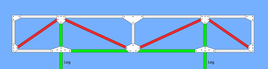
Figure 11. Basic concept for an ice bath fabricated for Biostasis Technologies. Red braces are under tension while green sections experience compression forces.The ice bath is entirely supported by legs in this diagram.
This design was very rigid, but I also wanted it to fold up for easy transportation, with no loose parts. To enable this, I added a hinge in each diagonal brace. The hinge could be locked or unlocked using a neat little gadget known as a draw catch. Figure 12 shows a closeup of a draw catch open, while Figure 13 shows it closed.
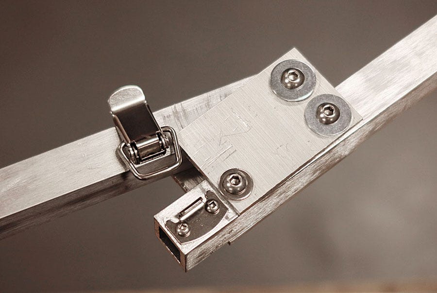
Figure 12. The hinge in a diagonal brace on the ice bath designed for Biostasis Technologies is secured by a draw catch.
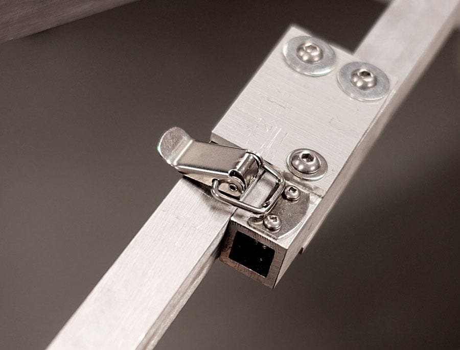
Figure 13. The lever of the draw catch turns to hold the catch closed.
Figure 14 shows where the draw catches are located, while Figure 15 shows one half of the ice bath partially folded for transportation, when the catches are released.
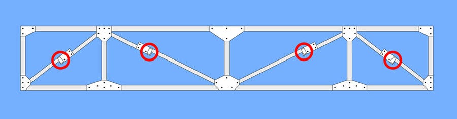
Figure 14. Locations of the draw catches.
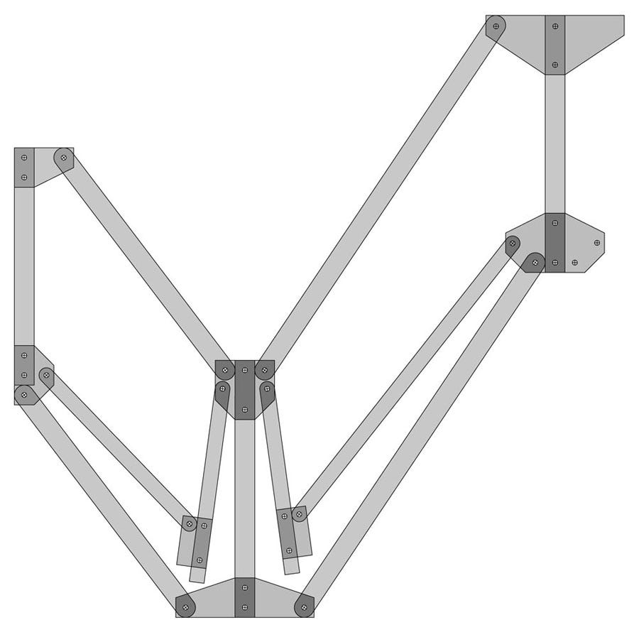
Figure 15. One-half of the ice bath, partially folded for transportation.
Since the braces all functioned as ties experiencing extension forces, you may wonder why the draw catches were necessary. After all, when a tie experiences an extension force, it is not going to fold up.
However, the ice bath was designed to be removable from its legs, in which case it would experience the opposite-ends scenario, shown in Figure 16. Without any legs to provide intermediate support, the forces reverse in the diagonal end braces. They have to withstand compression forces instead of extension forces, and will tend to fold under pressure. Therefore, the draw catches are essential.
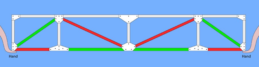
Figure 16. Compare with Figure 11 to see how the nature of the forces changes when the bath is lifted by its ends instead of resting on legs at intermediate points.
This creates an obvious failure mode: People using the bath may forget to secure all the draw catches. This might seem unlikely, as the process of unfolding the ice bath involves straightening each diagonal brace, bringing people’s hands into contact with the catches. When I tested the bath with volunteers, they did in fact remember to flip each catch into its locked position. Still, I regard the catches as a weak point.
On the other hand, any ice bath that can be collapsed or disassembled entails a risk of people failing to deploy it properly. I tend to believe that these risks are minimized if an ice bath is all in one piece, rather than in separate sections that have to be assembled. But that is a personal judgment call, and I won’t know if I’m right until competing designs of ice baths have been widely used in a variety of situations.
Lateral Forces
So far, I have only shown views of the Biostasis ice bath from the side, where vertical forces and deflection are most obvious. But now I would like you to imagine looking down at the bath from above. It is fitted with a liner, and the liner contains a substantial volume of water.
Under the influence of gravity, a pool of water on a horizontal surface will attempt to form a circle that spreads outwards. But an ice bath is not circular; it is a long, narrow rectangle. Consequently, water will push outward most forcefully around the middle of the ice bath, which also happens to be the location in the side rails that is most vulnerable to sideways deflection.
The magnitude of the outward force exerted by the water will increase if more water is added. I think this force is unlikely to bend the square-section aluminum tubing used in the rails, but each rail contains three pivoting joints, sandwiched between gusset plates. These joints are potential weak points that may conceivably allow the sides of the bath to bow outward. When the bath is lifted from the ends (in the opposite-ends scenario), compression forces along the horizontal rails will be maximized. So long as the rails form a straight line, they will resist these forces. But if the joints are slightly loose, and the water encourages the sections of the rails to bow outward, the compression forces will exacerbate this situation. If the rails become significantly misaligned, a runaway deformation can potentially lead to the sides of the bath splaying outward and the bath collapsing in the middle.
I took two measures to prevent this from happening. At intervals along the flat bottom of the bath, diagonal braces were added to maintain the sides in a vertical orientation. Also, some care was taken to prevent the pivoting joints from becoming loose.
Aluminum is a relatively soft metal. Consequently, some wear will tend to occur where aluminum tubing rotates around a steel bolt, as the threads of the bolt will scrape the surface of the aluminum. Consequently the joint will become loose, and now may wiggle one way or the other, so that a failure becomes increasingly likely over time. To prevent this, I inserted a stainless-steel sleeve in each joint, as shown in cross-section in Figure 17.
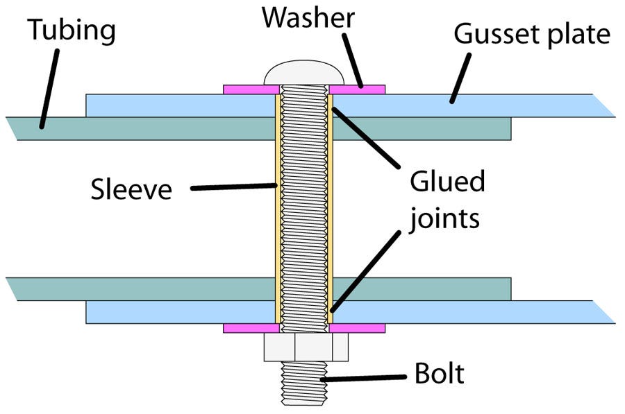
Figure 17. The steel sleeve around the bolt is colored yellow.
The sleeve fits tightly into the gusset plate, and cyanoacrylate glue is added to discourage it from rotating in the hole in the plate. The tubing now rotates around the smooth exterior of the sleeve.
I believe this minimizes the problem, but there is one more detail to mention, which is the method used to support the flat floor of the bath. This floor consists of ABS plastic, which is quite flexible. Therefore it has to be supported on horizontal aluminum tubes that span the width of the bath. These horizontal tubes function as short horizontal beams.
However, they are only 24" long, and now the third-power law works in my favor:
2 * 2 * 2 = k * d
Using the same tubing as in my original experiment, the deflection would be only 0.15 inches for a 24" beam instead of 0.5" for a 36" beam. My tests suggest that even if someone stands on just one of the beams, it will not bend significantly, and certainly not permanently.
I like to think that I have imagined all of the potential problems inherent in the truss design, but bearing in mind my estimates of the high load that an ice bath may carry, I hope that anyone who uses any design of this basic piece of equipment will be observant, watching out for anything that becomes loose or out of alignment. The rule should be very simple: People using cryonics standby-transport equipment should always notify the organization if they see anything that doesn’t look right. Feedback from personnel in the field is indispensable.
Legs and Wheels
One aspect of legs that I have avoided mentioning so far is that they are of limited use unless they have wheels. Unfortunately, legs that terminate in wheels introduce a whole new set of failure modes.
Imagine a person running along a dirt road. One of his feet encounters a small rock, at which point his forward momentum causes the upper half of his body to keep moving, while his toe remains stationary, in contact with the rock. The unfortunate person’s body now rotates around the rock until he becomes horizontal, lying face-down on the road.
Something similar can happen when a wheel hits an obstruction. Basically, if the obstruction is higher than half the height of the wheel (in other words, the obstruction is higher than the axle), the wheel is unlikely to roll over the obstruction; and if the wheel is attached to the leg of an ice bath, the bath may rotate in the same fashion as the person whose toe encounters a rock.
I see two ways to avoid this kind of catastrophe. Either use larger wheels, or require that the ice bath must be used on reasonably smooth surfaces.
Larger wheels will certainly help, although they will still be defeated by significant barriers, such as a curb at the side of a road. Also, they will greatly increase the empty-weight of the ice bath, and connecting them with the legs of the ice bath will be a challenge. Manufacturers supply wheels mounted on brackets made of heavy-gauge steel, but if we add our own steel plates or strips to mate the wheels with aluminum legs, this will just transfer the problem farther up the leg, where bending may occur.
The root of the problem is that when an ice bath has legs under it, most of the weight is now elevated at least three feet above the ground. The center of mass now has much more leverage.
Collapsible ice baths with legs have not been widely tested under adverse circumstances, as far as I am aware. In future cases, we will learn how this type of equipment is most likely to be used or abused in real-world conditions, and what precautions are necessary to guard against the type of wheel problems that I have described. Until these issues are clarified, the best compromise between the weight of a wheel and its ability to roll over obstacles is a matter for debate.
Conclusion
I believe that collapsible ice baths are necessary in field work. I think they should have legs raising them to a height which facilitates the activities of a standby-transport team, and I think the legs must terminate in wheels. However, these conveniences will inevitably require some basic precautions, even while team members are trying to act as rapidly as possible to achieve their goals.
Failure modes are inherent in all pieces of equipment, but remembering them, and avoiding them, is especially important when doing patient transport in an ice bath.
Charles, I admire your work on the evolution of the ice bath. As a former aircraft structural engineer I understand the challenges of stiffness and weight. The bending stiffnes of a beam is proportional to its cross-section’s moment of inertia. The height dimension of the beam’s cross-section factors as the 3rd power in the calculation. So beam height is everything in terms of stiffness. Fortunately there are very stiff lightweight beams that you can purchase from 8020.net and have cut to length. The 8020 t-slotted 1x2” extrusion (https://8020.net/1020.html) would work for a single beam ice bath. The cool thing about the 8020 structural system is that they have a wide variety of connectors, hinges, handles, and so forth available that attach to the beams with screws. One could design the complete ice bath structure, and order cut-to-length beams and attachments, and assemble it all with only a screwdriver. This is the go-to solution for building custom structures and is used widely now in industry. I know this sounds like a sales pitch, but it’s really that good. I’m available to discuss and assist with a next gen portable ice bath if there’s interest. Contact: robwilkes@me.com, https://www.facebook.com/robert.wilkes.5055.
Wow...fabulous attention to detail by the legendary Charles Platt. It is easy for many of us to take for granted the unique challenges in the Cryonics field, and how much thought and effort needs to be expended to create optimal protocols and equipment. This article explains in detail the challenges of creating a portable ice bath. Bravo for this article, Charles!